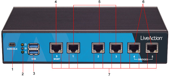
LiveWire Edge rear panel
Item | Indicator, Button, or Connector | Description |
|---|---|---|
1 | Mini-USB Port | The Mini-USB port (console port) lets you connect to another computer terminal for advanced diagnostics or recovery access using a mini-USB console cable (not included with LiveWire Edge) connected from the USB port on your PC/laptop to the Mini-USB Port on the rear panel of LiveWire Edge. See Connecting to LiveWire through the serial port. |
2 | Storage/Status/Power LEDs | Storage: If the LED blinks, it indicates data access activities; otherwise, it remains off. Status: When LiveWire Edge is first powered on, the LED momentarily blinks green, and then remains off. Power: If the LED is on it indicates that the system is powered on. If it is off, it indicates that the system is powered off. |
3 | USB 3.0 Ports | The USB ports are reserved for future expansion. |
4 | ‘MGMT’ Port | This 1GbE Ethernet port is the management port that lets you configure LiveWire Edge (see Using the LiveAdmin utility). Connect a standard Ethernet cable from your network to the ‘MGMT’ port. |
5 | ‘1–3’ Ports | These 1GbE Ethernet ports are used for capturing packets from your network. Connect a standard Ethernet cable from your network to the desired port on LiveWire Edge. |
6 | ‘4–5 Bridged’ | These 1GbE Ethernet ports are configured as a bridge and are used when you want to insert LiveWire Edge in-line between two network devices. This configuration allows the capture of traffic flowing between the two network nodes without requiring a tap. In this implementation, packets enter LiveWire Edge through one of the bridge ports, and then exit LiveWire Edge through the remaining bridge port. Essentially, any traffic that gets to one bridge port is copied to the other bridge port. In cases where power is turned off or is lost to LiveWire Edge, the two bridge ports are connected as if they are a wire (‘fail to wire’), so Internet connectivity is not lost. To establish the bridge, connect standard Ethernet cables so that LiveWire Edge is between your cable modem (Internet connection) and the LAN. One of the bridge ports on LiveWire Edge is connected to the cable modem, while the other bridge port is connected to the LAN. Both bridge ports must be connected in this fashion in order to properly establish the bridge. Do not connect each of the bridge ports to the same IP routed network; otherwise, a routing loop is created, and can cause the network to be inoperable. Note: When powering the LiveWire Edge on or off, there will be a short network disruption when the hardware bypass (bridge port) is enabled or disabled. |
7 | Port LEDs | The two LEDs on the bottom of the Ethernet ports light to indicate activity. A green and yellow LED light to indicate a connection has been established. A flashing yellow LED indicates data access activities. |